Circuit Boards and Electronics
Led by Miles Krawitz
The PCB (Printed Circuit Board) is what bridges the gap between the code and the physical parts of the rocket (TVC and pyro channels). The main challenge is fitting all the components on the board and having functional wiring.

Rectangle 1.0
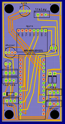
This was the first Electronics bay (E-Bay) we made. Miles designed the PCB in Fritzing (PCB CAD software), and it was relatively basic: it ran on an Arduino Nano microcontroller, used an MPU-6050 gyro/acceleromer for attitude sensing, and it could control two servos, just enough for one TVC. We used this E-Bay at our first launch, and it worked well enough for a first prototype.

Circle 5.0
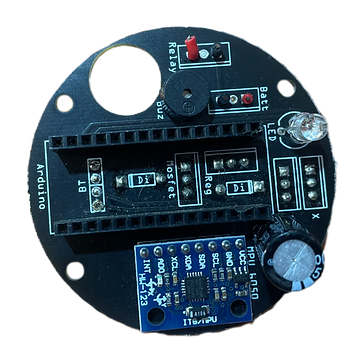
After launching using the Rectangle 1.0 which mounted vertically in the rocket, we decided to design the next board to be mounted horizontally for easier user interfacing and to try to make the gyro drift less. In an effort to ease troubleshooting, I added an RGB LED that changes color depending on the flight stage. Like the Rectangle 1.0, this board can control two servos, however it also has one pyro channel.

Circle 8.0
We flew this board at the second launch. It is similar to the Circle 8.0, however there are a few differences. It mainly optimized the wiring and spacing on the board to allow room for three servo outputs and three pyro channels. It also fixed a small wiring issue with the gyro. The day before launch, the mosfets that control the pyro channels weren't working, so, after realizing we had been wiring them wrong this entire time (big L moment), Miles had to sketchily rewire the mosfets using hot glue and jumper wires.

Circle 10.0
We flew this board at our successful third launch. Miles included an array of helpful components including a BMP-180 barometer, an SD-card module (for data logging), two pyro channels, and two servo channels. Also, for easier user interfacing, he added a main toggle switch, a pyro toggle switch, and a launch button that would start a 30-second launch countdown timer when pressed.

